Avr2011 kit
From HacDC Wiki
Kit Contents
You will need:
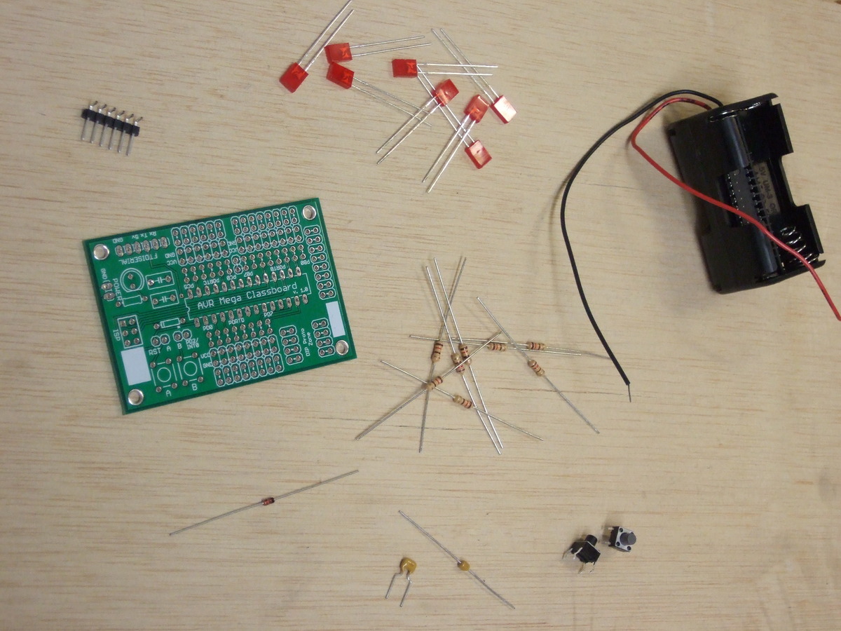
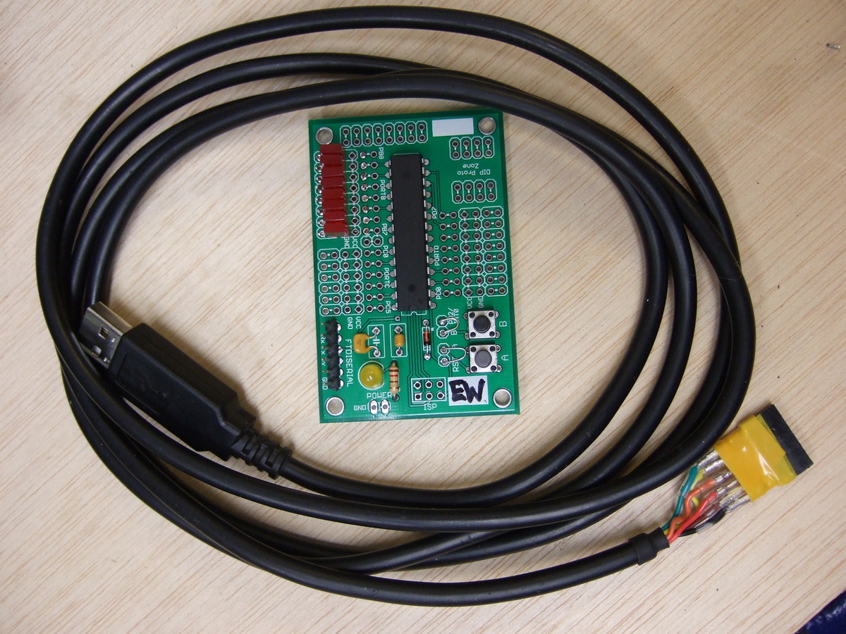
1) AVR ATMega microcontroller 2) AVR Classboard printed-circuit-board 3) Eight resistors (~120 ohm) 4) Eight LEDs (I like the small square ones) 5) 1 uF capacitor 6) 0.1 uF capacitor 7) Two push buttons 8) 6-pin header to connect the FTDI serial cable 9) A small-signal diode for backward-power protection (optional, but certainly won't hurt)
(D'oh! I left the AVR out of the photo. You should have one.)
A Brief Tour of the Board
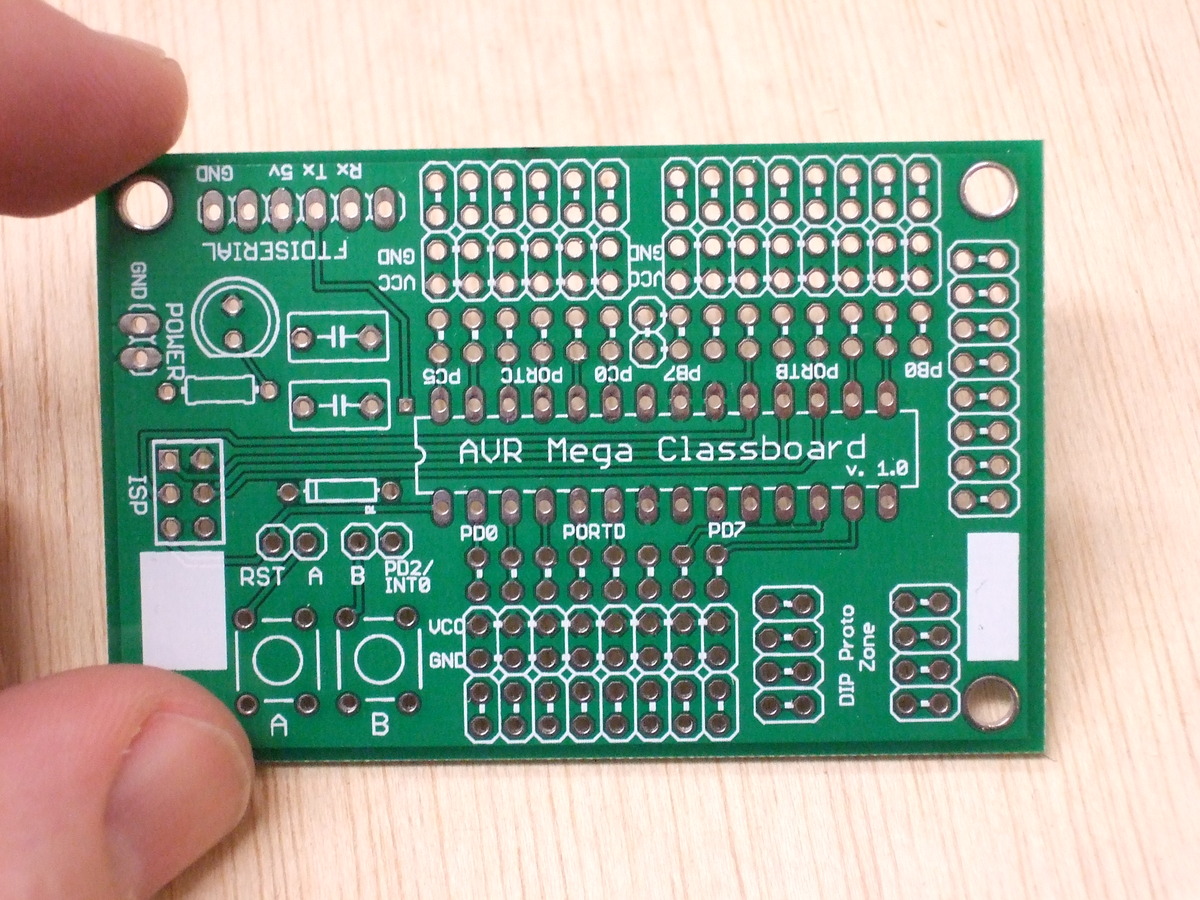
Before you start assembling anything, have a look at the printed circuit board.
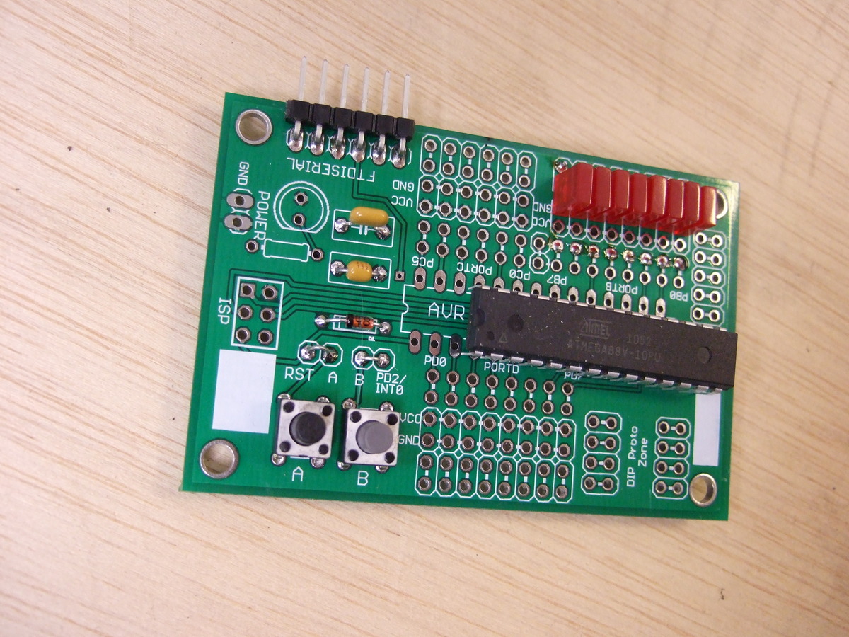
Big and bold in the center is the location for the AVR chip. Notice the notch in the silkscreen at one end? That corresponds to a notch on the top of the AVR chip, and helps you get it in the right orientation when the time comes.
Just to the outside of the AVR chip itself, you'll see two rows of holes labelled for the port/pin combinations that appear in the datasheet. For instance, just below the chip see the two rows labelled PORTD, and PD0 -- PD7. See how there are tiny white lines connecting the two rows of holes, pairwise? Those indicate that the two holes are electrically connected to each other. This was a convenience -- you can solder two things easily to each AVR pin. One side of the chip has PD0-PD7, the other has PB0-PB7 and PC0-PC6.
Just outside of the AVR connection points, you'll see two more rows of holes, labelled VCC and GND respectively. GND is connected to the board's ground plane, and so is at 0V. VCC is connected to the board's power supply and is whatever voltage you're using to drive the whole mess -- In class, I'll refer to this as VCC or I usually just call this 5V.
And finally, at the edge of the board is another pair of rows of holes. These are electrically connected in pairs, and are just there to allow you to connect things together easily. For the LED array, we'll use these paired holes to connect the resistor to the positive end of the LED.
Other stuff:
To the left of the AVR, there are holes for two buttons, a protection diode, power-supply buffering capacitors, an optional power LED and its resistor, a 3x2 SPI programming header, and the 6-pin inline FTDI cable.
Below the AVR chip area and to the right, there's more prototyping space -- just sets of holes electrically connected to each other in ways to facilitate soldering stuff up.
The power LED and it's associated LED are optional and included for your creative use/abuse. Everyone should solder the coolest LED they can find in here, with a 100-1k ohm resistor, depending on how bright you want it.
And those white areas? They're for writing your initials on. Or notes. Tiny, little notes.
Assembling the Kit
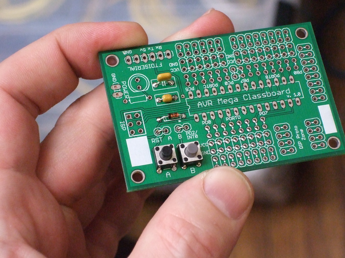
1) To get your feet wet soldering, install the two capacitors. They can go in either capacitor position, and are non-polarized (can go in either way). When you clip off the leads from the capacitors, save the wire for the next step.
2) Now install the two pushbuttons. They're oblong, but there's no top or bottom.
3) Solder in the protection diode. Notice that it's polarized, with a black band on the diode itself corresponding to the little band in the silkscreen.
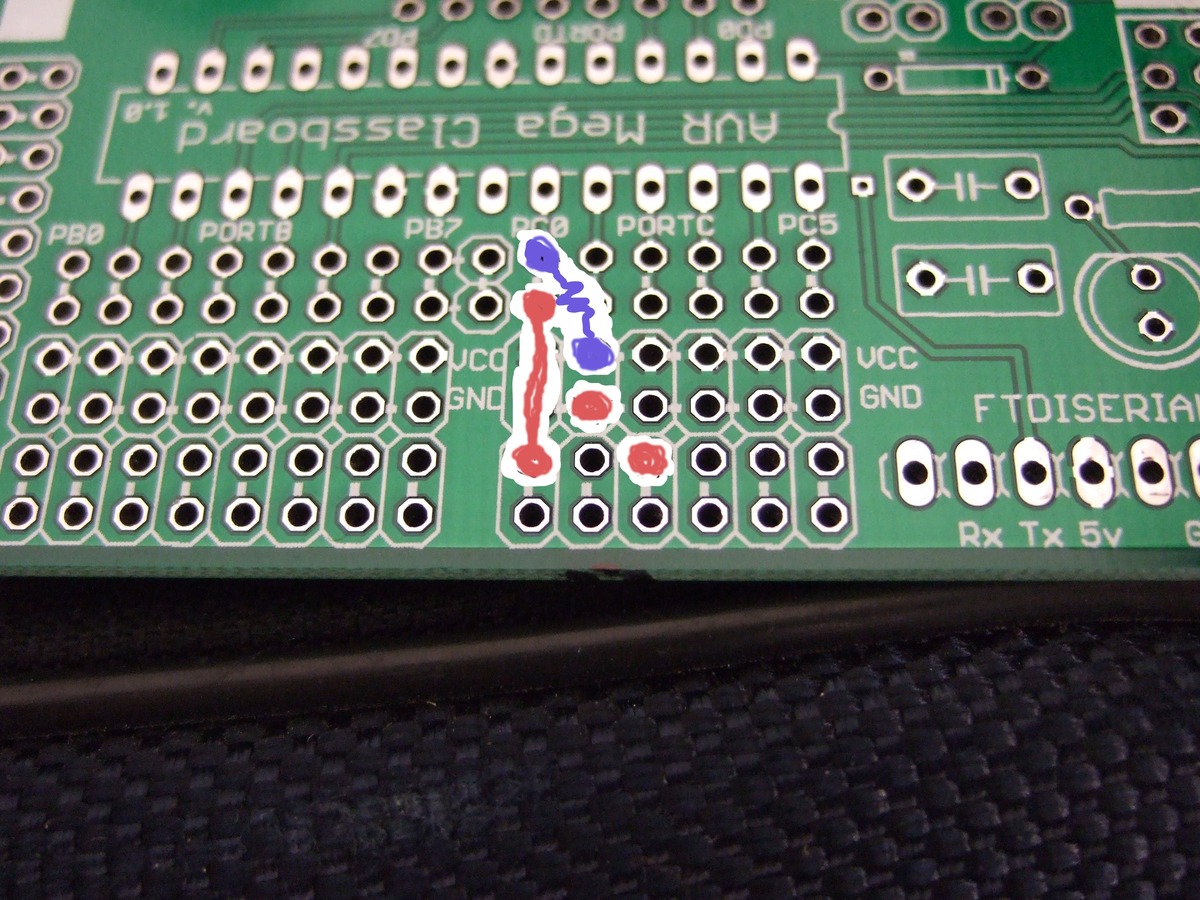
4) Above the buttons, there are two pairs of holes -- these connect the button to the pin on the AVR when they're jumpered together. (I did this for flexibility so that you could connect the buttons up to other pins later as you wish.) Take two of the leads you saved in step 1) and connect each pair of holes together.
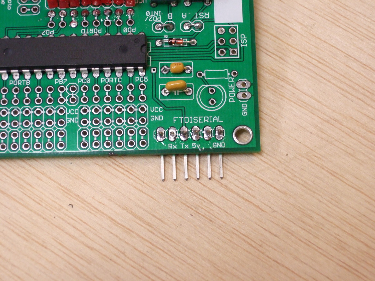
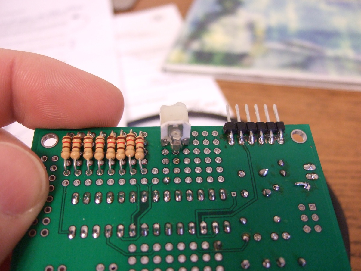
5) Solder in the 6-pin header for the FTDI cable. Rather than doing it the way I did (which covers the labels on the circuit board) why not mount the header on the bottom side like Ed did?
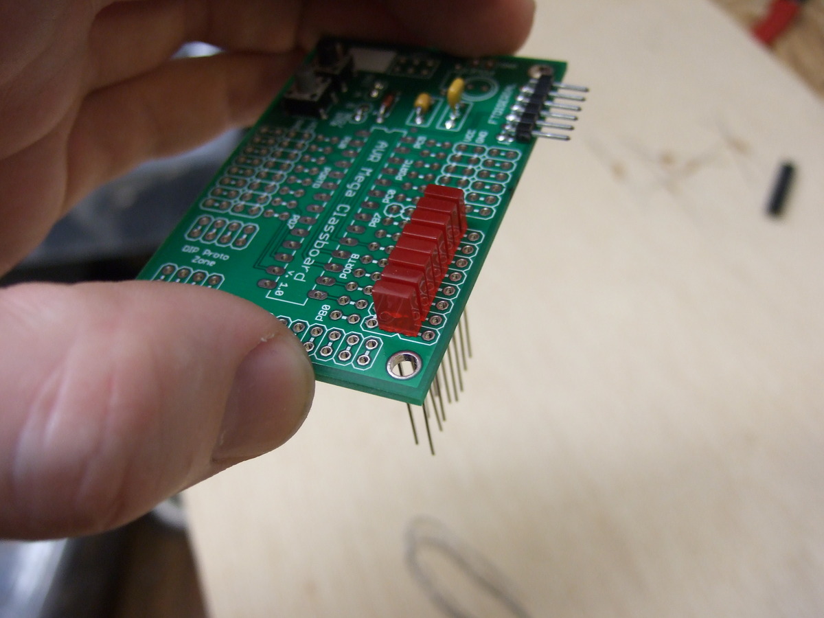
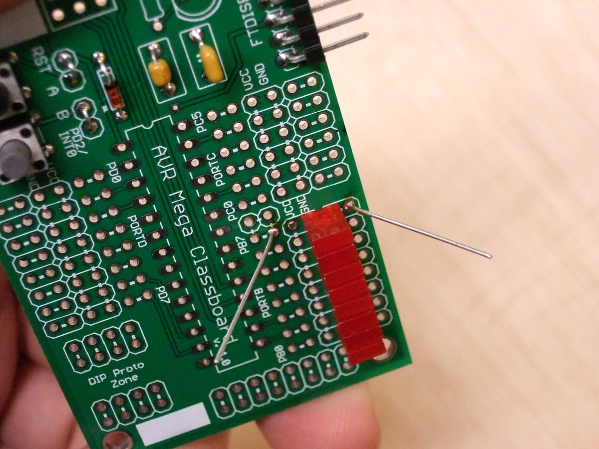
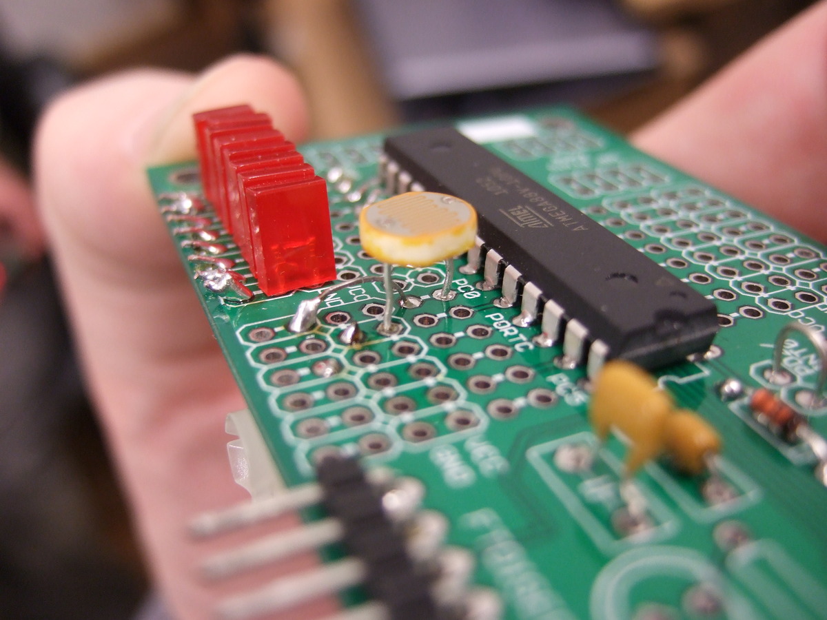
6) Now start on the LEDs -- in PORTB pins PB0 through PB7. They _are_ polarized, and you'll notice that one lead is longer than the other. The short lead gets connected to ground, while the long lead will eventually connect through a resistor to the AVR output pins. (Resistors soldered in next step.) Place the LEDs so that their short leads are in the ground strip (labelled GND), and the long lead is in one of the outside rows of hookup holes. Orientation matters here. Double-check it before soldering?
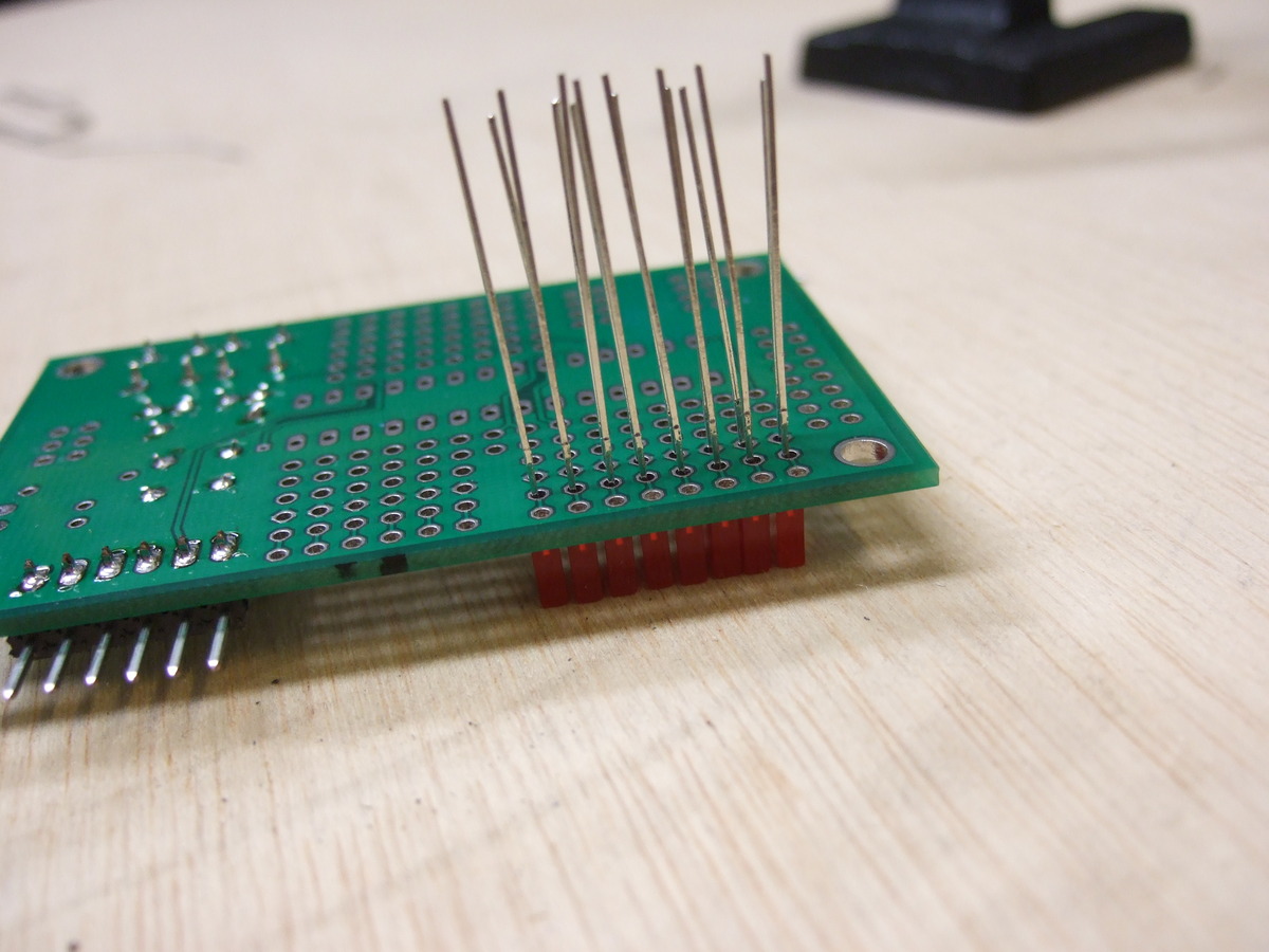
For aligning the LEDs, I had success putting them all face-down on the table, and using the fact that they have rectangular faces. Pro-tip: solder one pin on each LED, make sure they're in a nice line, and re-heat any that you need to wiggle into place. Then solder in the second pin on each LED.
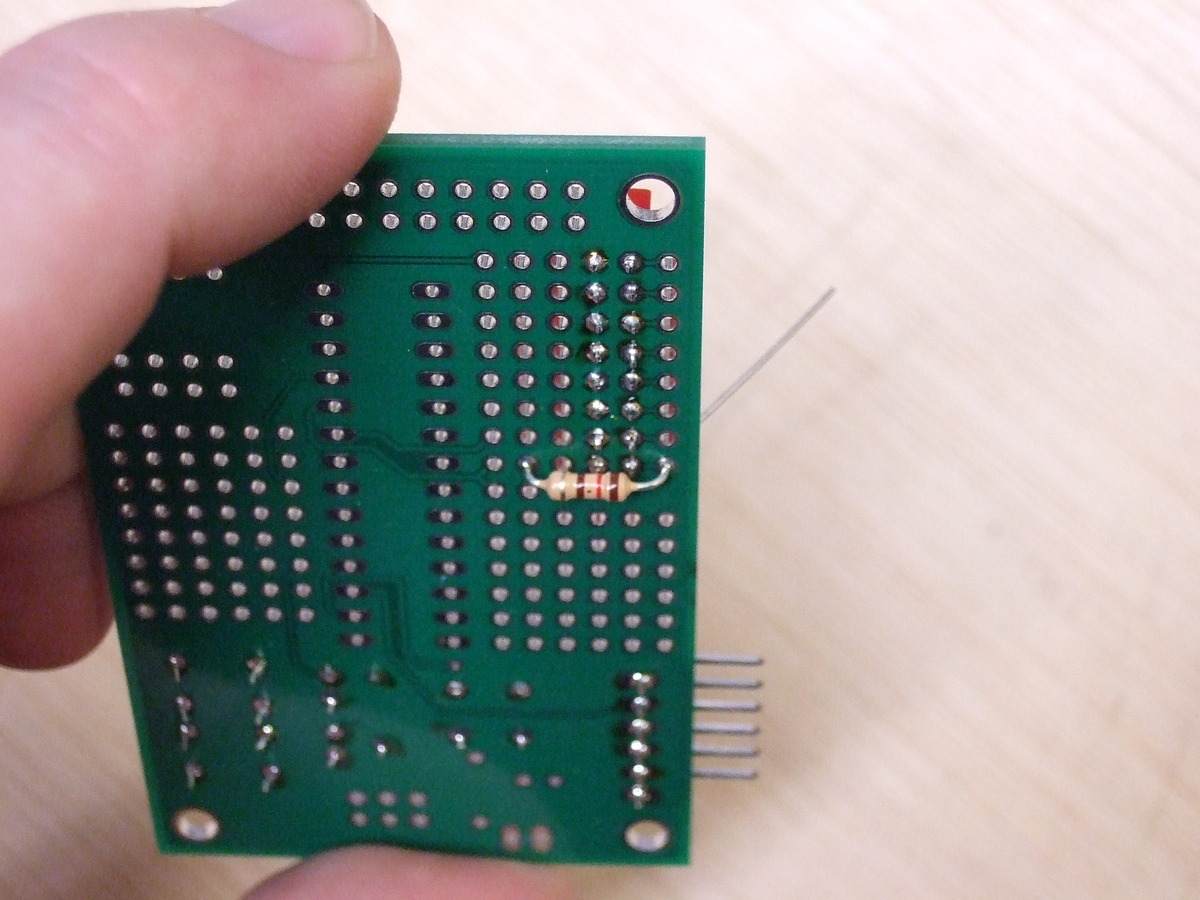
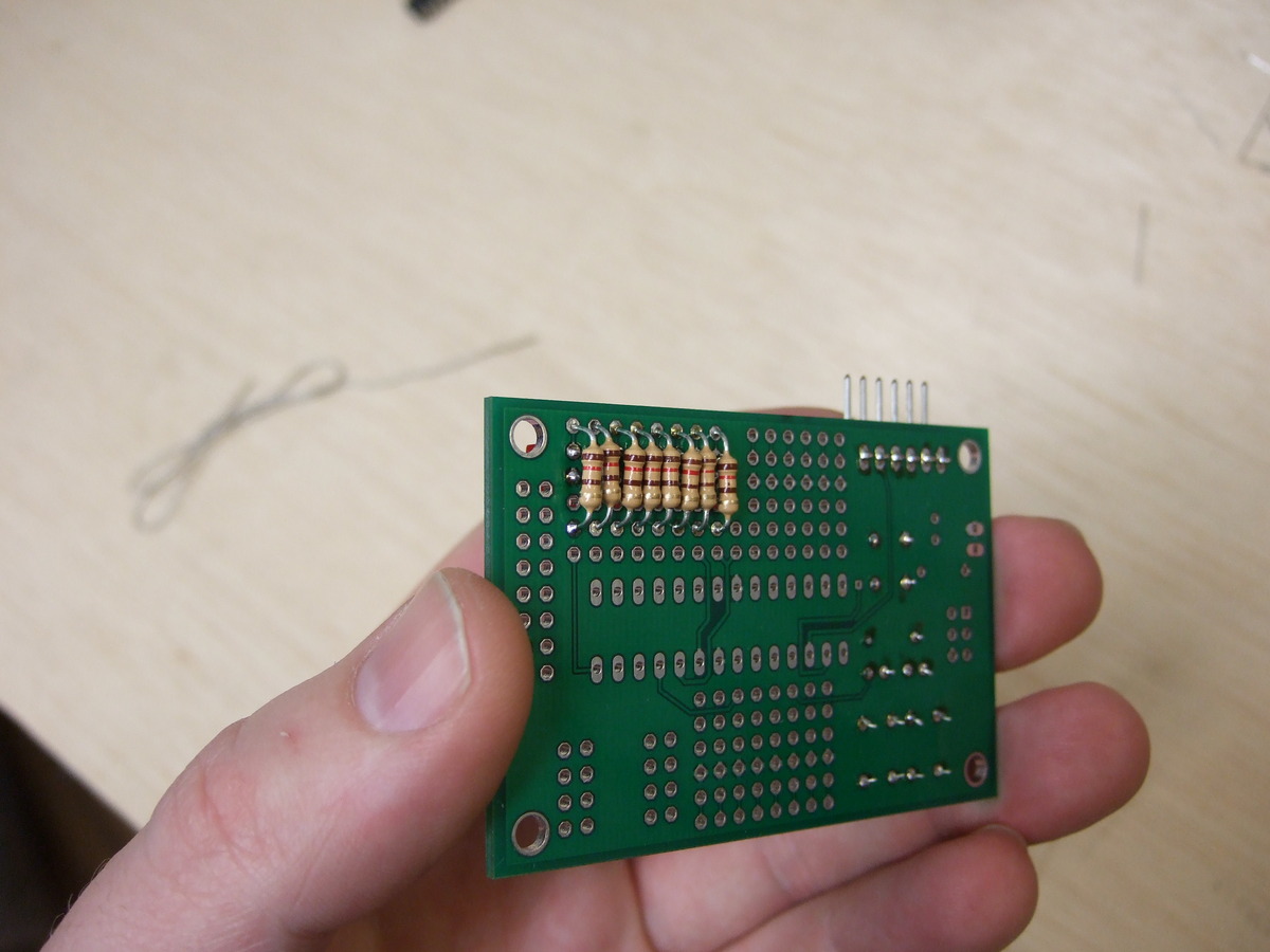
7) Once you've done the LEDs, you can solder in their resistors. These fit most easily and cleanly on the underside of the board, so you'll want to trim off the extra leads from the LEDs before installing. You want to solder each resistor to the outside strip of holes that connected to the positive (long) pin of the LEDs, and the other end of the resistor to the pins of the AVR. Notice that you're working on the back-side of the board! Double-check that you're not connecting the resistor to the VCC line that is closest to the LED.
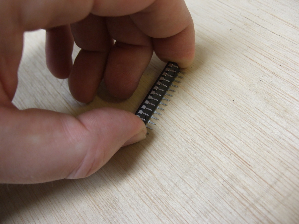
8) At this point, you can install the chip. They come from the factory with the pins splayed out a little bit -- you can lean the chip into a tabletop to straighten the pins out. Place the chip with the notch on the top of the chip corresponding to the notch in the silkscreen. Double-check. Solder.
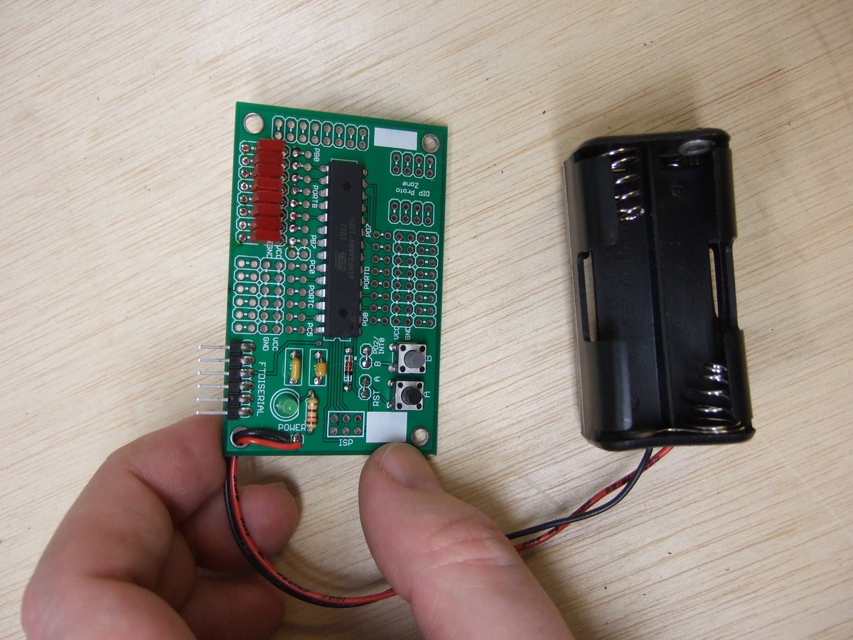
9) Optional fun stuff: Feel free to solder in an artistic power LED and its resistor. (Note the polarization. Short pin downwards, or notice that there's a flat-spot on the LED flange.) Write your name on it. Wire up the battery (black wire to GND).
10) You should now be ready to flash in your first program. Hooray. From here on it's (mostly) firmware!

