STL to SCAD: Difference between revisions
From HacDC Wiki
Ubuntourist (talk | contribs) (Signature and more detail) |
Ubuntourist (talk | contribs) (Link to OpenSCAD manual. Formatting clean-up.) |
||
| Line 5: | Line 5: | ||
Sadly, these are impossible to work with. | Sadly, these are impossible to work with. | ||
== Stupid pet tricks with OpenSCAD == | == Stupid pet tricks with OpenSCAD == | ||
The prerequisite here is that you're already somewhat familiar with basic shapes, transformations, differences and unions. If not, get thee hie to the [http://www.openscad.org/documentation.html OpenSCAD manual] and read up. | |||
* These next three lines import and flatten the STL. The result can be exported as SVG, DFX, or several other formats. I saved it as both bottom.svg and bottom.dfx. | * These next three lines import and flatten the STL. The result can be exported as SVG, DFX, or several other formats. I saved it as both bottom.svg and bottom.dfx. | ||
projection() | projection() // Flatten | ||
translate([0, 0, -10]) | translate([0, 0, -10]) // The original STL appeared "hover" mid-air. This brought it back to earth. | ||
import("assembly_v4_rev3.stl"); | import("assembly_v4_rev3.stl"); // STL unzipped from the Thingiverse download. | ||
:resulting in: | :resulting in: | ||
| Line 22: | Line 24: | ||
* Although extruding imported DXF files works after a fashion, it's still not really editable source code. It ain't pretty, but there's a fix for that as well. The SVG produced from the '''projection()''' and export is a series of polygons, each of which is a series of point coordinates. Look at the '''path''' element of the SVG: | * Although extruding imported DXF files works after a fashion, it's still not really editable source code. It ain't pretty, but there's a fix for that as well. The SVG produced from the '''projection()''' and export is a series of polygons, each of which is a series of point coordinates. Look at the '''path''' element of the SVG: | ||
<svg width="108" height="96" | |||
viewBox="-62 -50 108 96" | |||
xmlns="http://www.w3.org/2000/svg" | |||
version="1.1"> | |||
<path d="M x1,y1 L x2,y2 L x3,y3 ... L xN,yN z | |||
M x1,y1 L x2,y2 L x3,y3 ... L xN,yN z | |||
... | ... | ||
M x1,y1 L x2,y2 L x3,y3 ... L xN,yN z" | |||
stroke="black" fill="lightgray" stroke-width="0.5"> | |||
</svg> | |||
* OpenSCAD polygon definitions are lists of points enclosed in brackets [point, point, point, ..., point]. Each point is an X, Y coordinate pair, also enclosed in brackets [X,Y]. So, the full shape looks like [[X,Y], [X,Y], [X,Y], ..., [X, Y]]. | * OpenSCAD polygon definitions are lists of points enclosed in brackets [point, point, point, ..., point]. Each point is an X, Y coordinate pair, also enclosed in brackets [X,Y]. So, the full shape looks like [[X,Y], [X,Y], [X,Y], ..., [X, Y]]. | ||
| Line 42: | Line 44: | ||
* The result should be: | * The result should be: | ||
polygon([[x1, y1], [x2, y2], [x3, y3], ... [xN, yN]]); | |||
polygon([[x1, y1], [x2, y2], [x3, y3], ... [xN, yN]]); | |||
... | |||
polygon([[x1, y1], [x2, y2], [x3, y3], ... [xN, yN]]); | |||
* I suspect, in general, the first polygon will be the general outline, and the subsequent polygons will be "holes" in the shape. So, surround the whole thing with a '''difference()''' and add a linear_extrude() to get some height: | |||
linear_extrude(height=10) { // e.g. 10mm high | |||
difference() { | |||
polygon([[x1, y1], [x2, y2], [x3, y3], ... [xN, yN]]); | polygon([[x1, y1], [x2, y2], [x3, y3], ... [xN, yN]]); | ||
polygon([[x1, y1], [x2, y2], [x3, y3], ... [xN, yN]]); | polygon([[x1, y1], [x2, y2], [x3, y3], ... [xN, yN]]); | ||
... | |||
polygon([[x1, y1], [x2, y2], [x3, y3], ... [xN, yN]]); | polygon([[x1, y1], [x2, y2], [x3, y3], ... [xN, yN]]); | ||
} | |||
} | |||
* Voila! Done! You now have a parametric representation, albeit an ugly, incomplete one, of what was once an STL file. | * Voila! Done! You now have a parametric representation, albeit an ugly, incomplete one, of what was once an STL file. | ||
Revision as of 15:30, 18 August 2017
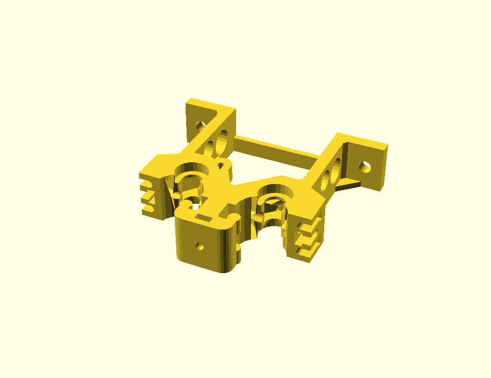
Suppose you have an STL for a part to be 3D printed. In this case, an HST double bolt bowden extruder V4 assembly downloaded from: https://www.thingiverse.com/thing:515747/
 (Click the image for a larger view. For the full 360, watch the movie.)
Sadly, these are impossible to work with.
Stupid pet tricks with OpenSCAD
The prerequisite here is that you're already somewhat familiar with basic shapes, transformations, differences and unions. If not, get thee hie to the OpenSCAD manual and read up.
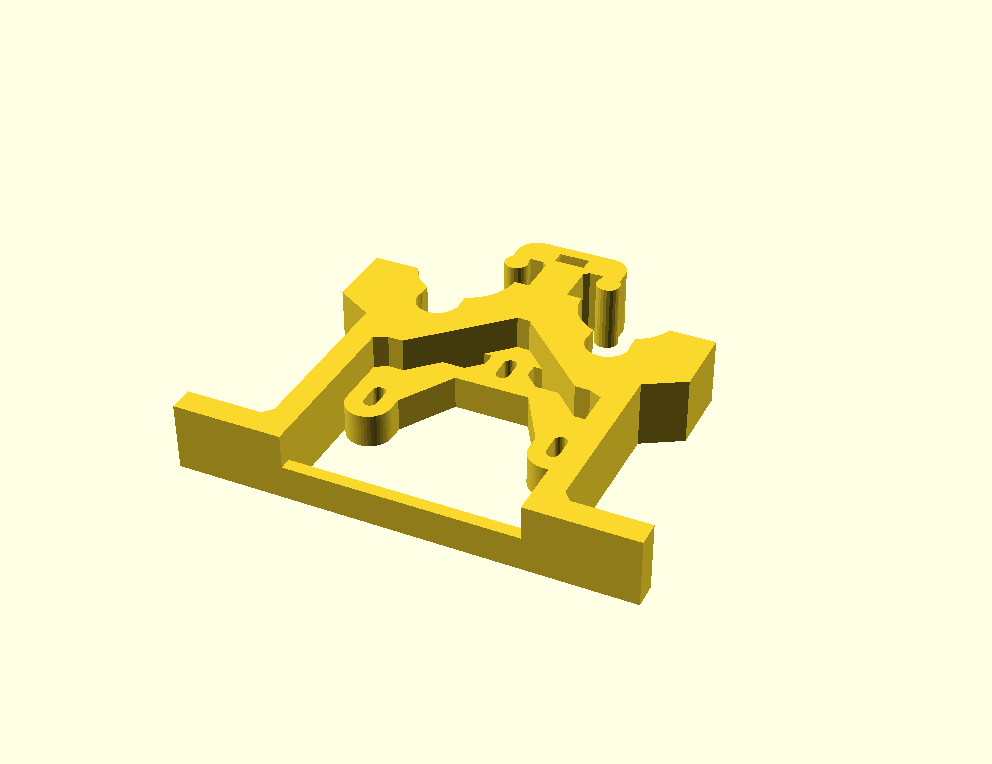
- These next three lines import and flatten the STL. The result can be exported as SVG, DFX, or several other formats. I saved it as both bottom.svg and bottom.dfx.
   projection()                         // Flatten
     translate([0, 0, -10])             // The original STL appeared "hover" mid-air. This brought it back to earth.
       import("assembly_v4_rev3.stl");  // STL unzipped from the Thingiverse download.
- resulting in:
 (Note: This is an SVG rather than a DFX, but the concept / result is nearly the same.)
- The DFX (at least) can be read in again and extruded:
   linear_extrude(height=10)
     import("bottom.dxf");
- Since the object in question changes shape at different "heights" several layers need to be cut away in order to get a newer shape. In OpenSCAD this is done by creating another shape and subtracting it from the initial shape with a difference() operation.
- Unfortunately, operations on STL files can go wrong because STL files are often produced sloppily. Fortunately FreeCAD is one of the programs that can repair STL files. See Sli3r's page on repairing models for instructions. (The STL file used in this document had to be iteratively repaired multiple times before FreeCAD reported no errors.
- Although extruding imported DXF files works after a fashion, it's still not really editable source code. It ain't pretty, but there's a fix for that as well. The SVG produced from the projection() and export is a series of polygons, each of which is a series of point coordinates. Look at the path element of the SVG:
   <svg width="108" height="96"
        viewBox="-62 -50 108 96"
        xmlns="http://www.w3.org/2000/svg"
        version="1.1">
   <path d="M x1,y1 L x2,y2 L x3,y3 ... L xN,yN z
            M x1,y1 L x2,y2 L x3,y3 ... L xN,yN z
                ...
            M x1,y1 L x2,y2 L x3,y3 ... L xN,yN z"
         stroke="black" fill="lightgray" stroke-width="0.5">
   </svg>
- OpenSCAD polygon definitions are lists of points enclosed in brackets [point, point, point, ..., point]. Each point is an X, Y coordinate pair, also enclosed in brackets [X,Y]. So, the full shape looks like [[X,Y], [X,Y], [X,Y], ..., [X, Y]].
- Edit the SVG with the following rules:
- The opening and closing svg tags at the beginning and end of the file should be removed as should the stroke="black" fill="lightgray" stroke-width="0.5" attributes at the end of the path element. Really, everything except the contents of the d attribute of the path element should be stripped away -- although the viewbox, height and width attributes in the initial opening svg tag may offer further clues at a later date.
- M are move to (pen up) command and marks the start of a polygon. Convert them to polygon([
- L are line to (pen down) command. Eliminate them -- but not the coordinate pairs that follow each of them.
- number pairs are X and Y coordinates and should be enclosed in brackets and all but the last should be followed by a comma. [X,Y],
- z finishes off the current polygon. Convert each to ]);
- The result should be:
   polygon([[x1, y1], [x2, y2], [x3, y3], ... [xN, yN]]);
   polygon([[x1, y1], [x2, y2], [x3, y3], ... [xN, yN]]);
       ...
   polygon([[x1, y1], [x2, y2], [x3, y3], ... [xN, yN]]);
- I suspect, in general, the first polygon will be the general outline, and the subsequent polygons will be "holes" in the shape. So, surround the whole thing with a difference() and add a linear_extrude() to get some height:
   linear_extrude(height=10) {                               // e.g. 10mm high
     difference() {
       polygon([[x1, y1], [x2, y2], [x3, y3], ... [xN, yN]]);
       polygon([[x1, y1], [x2, y2], [x3, y3], ... [xN, yN]]);
           ...
       polygon([[x1, y1], [x2, y2], [x3, y3], ... [xN, yN]]);
     }
   }
- Voila! Done! You now have a parametric representation, albeit an ugly, incomplete one, of what was once an STL file.
There's still a LOT of work to be done for holes that are not completely vertical. Completely horizontal holes are gonna be a BITCH! In fact any odd changes in the Z direction will be trouble. Some of that trouble can be solved by more difference() stanzas in the original STL, while others may be ferreted out by 90° and 180° rotations along various axis, possibly combined with difference().
The end result, produced by fullish.scad (the combination of bottom.scad and top.scad):
--Ubuntourist (talk) 08:20, 18 August 2017 (PDT)

