BiosignalAmplifier: Difference between revisions
From HacDC Wiki
No edit summary |
|||
| (One intermediate revision by the same user not shown) | |||
| Line 2: | Line 2: | ||
[[File:Mirage335BiosignalAmplifierHardware.jpg|right]] | [[File:Mirage335BiosignalAmplifierHardware.jpg|right]] | ||
=Status= | =Status= | ||
Operational | Operational. Use the dry (gold pin header) electrodes for now, saline electrodes will be sealed in hot glue soon. | ||
=Usage= | =Usage= | ||
# Connect the USB port to a computer with the [http://mirage335. | # Connect the USB port to a computer with the [http://mirage335-site.member.hacdc.org:6380/wiki/Category:BiosignalProcessor BiosignalProcessor] software installed. Primarily, this software depends on [http://www.mega-nerd.com/libsndfile/ libsndfile] and [http://www.baudline.com/ baudline]. | ||
# Launch the [http://mirage335. | # Launch the [http://mirage335-site.member.hacdc.org:6380/wiki/Category:BiosignalProcessor BiosignalProcessor] software. Noise floor should be approximately -100dB. | ||
# All sponge electrodes need to be wet, preferably with saline. This includes the reference electrode with a large yellow sponge, and the green sponge electrodes. | # All sponge electrodes need to be wet, preferably with saline. This includes the reference electrode with a large yellow sponge, and the green sponge electrodes. | ||
# Connect the SATA data cables as shown in the photo. These are actually used as shielded carriers for power and analog signals. | # Connect the SATA data cables as shown in the photo. These are actually used as shielded carriers for power and analog signals. | ||
| Line 39: | Line 39: | ||
* The BNC analog output on the host board is designed for connection to an oscilloscope. | * The BNC analog output on the host board is designed for connection to an oscilloscope. | ||
* Signal overload will trigger the green LED on the host board to flash. | * Signal overload will trigger the green LED on the host board to flash. | ||
* HacDC has a [http://mirage335. | * HacDC has a [http://mirage335-site.member.hacdc.org:6380/wiki/BiosignalSimulator BiosignalSimulator] on the test cart, which generates synthetic common-mode and differential-mode signals. | ||
=Safety= | =Safety= | ||
| Line 71: | Line 71: | ||
Additional documentation available on the project's webpage at: | Additional documentation available on the project's webpage at: | ||
http://mirage335. | http://mirage335-site.member.hacdc.org:6380/wiki/Mirage335BiosignalAmp | ||
==Copyleft== | ==Copyleft== | ||
Latest revision as of 03:07, 2 September 2016
Status
Operational. Use the dry (gold pin header) electrodes for now, saline electrodes will be sealed in hot glue soon.
Usage
- Connect the USB port to a computer with the BiosignalProcessor software installed. Primarily, this software depends on libsndfile and baudline.
- Launch the BiosignalProcessor software. Noise floor should be approximately -100dB.
- All sponge electrodes need to be wet, preferably with saline. This includes the reference electrode with a large yellow sponge, and the green sponge electrodes.
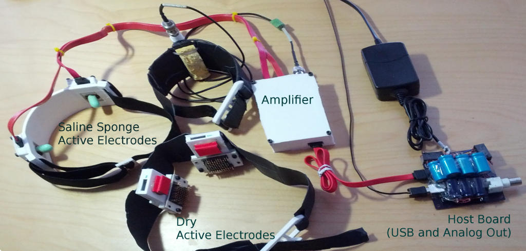
- Connect the SATA data cables as shown in the photo. These are actually used as shielded carriers for power and analog signals.
- Plug in the 12V wall wart. This enables the medically isolated RECOM RS-1212D power supplies.
- Noise floor should now be approximately -80dB.
- Cautiously, connect yourself to the Biosignal Amplifier. The BNC connectorized yellow sponge electrode is a reference, and may be connected anywhere on the body, preferably the right leg for electrocardiography, or arm for electroencephalography. The other two electrodes pickup the actual signal, and should be placed near the signal source.
Signal Sources
The pickup electrodes (either the green sponges and headband or dry pin header based electrodes) may be placed at a variety of locations to obtain biosignals in realtime.
- Placing the electrodes hand-to-hand or across the chest should obtain clear, strong electrocardiography (ECG, heartbeat) signals.
- With eyes closed, and pickup electrodes on the back of the head, four out of five participants will show an approximately 10Hz alpha rhythm, usually above -60dB on the chart.
- Across the forehead, electrooculography (EOG, eye movement) signals become dominant.
- Across any major contracted muscle (eg. forearm), random noise will be observed. This is an electromyography (EMG, muscle activity) signal.
- While sleeping, delta rhythms should appear at 90 minute intervals across the parietal (top of the head) and frontal (forehead) lobes. This has yet to be experimentally verified.
Captured Data Samples
Heartbeat
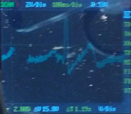
Captured on a DSO Nano oscilloscope from the analog (BNC) output.

Alpha Rhythm
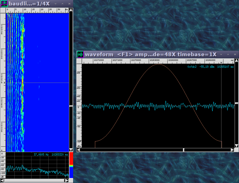
Alpha waves (EEG brainwaves) captured from occipital lobe with eyes closed. USB output was used directly. Notice the ~10Hz signal.
 Low-frequency noise to the left is expected to go away when a better transformer is used, or electrodes are better positioned.
Assistance
Drop by HacDC's IRC channel and ping mirage335 .
Troubleshooting
- The older dry active electrodes, based on gold plated pin headers, are somewhat easier to use than the green saline sponge electrodes. However, they require significant pressure to function properly, particularly for EEG use, which some users find uncomfortable.
- When in doubt, look for an electrocardiograph (ECG heartbeat) signal. Heartbeats are among the most available, strongest, clearest indicators of a working biosignal amplifier.
- The BNC analog output on the host board is designed for connection to an oscilloscope.
- Signal overload will trigger the green LED on the host board to flash.
- HacDC has a BiosignalSimulator on the test cart, which generates synthetic common-mode and differential-mode signals.
Safety
Reasonable safety features have been included. However, there are still some things to be aware of:
- Just 1mA of current for 1ms across the heart is most likely to be fatal. Take no chances.
- DO NOT operate high-power RADIO equipment (ie. our amateur radio station) while connected to the BiosignalAmplifier. High frequency radio transmissions will penetrate the isolation amplifier, which is to say you are an RF ground.
- DO NOT connect to external power in bad weather. Nearby lightning strikes will penetrate the isolation amplifier, and HacDC is not known to have excellent power quality.
- Excessive saline might contact the power supply rails in the active electrodes if the sealant has broken down. If in doubt, check the electrodes for voltage with a multimeter before using. Anything above 0.6V indicates a fault has occurred.
- Try not to leave any of the SATA cables partially connected while the system is on. In theory, the system might be damaged if just one or two of the supply rails (Vcc, GND, or Vee) are disconnected.
- No claim of liability is made by anyone. Your accident is your accident. Use common sense. If you don't understand the safety features and limitations, don't use this circuit.
Cost
Total cost of replacement is ~$300 and ~60 hours. Please don't break our BiosignalAmplifier!
Lending Policy
Qualified HacDC members are invited to borrow the BiosignalAmplifier, particularly for sleep research. Please update the status section when borrowing. Also be careful to keep all safety concerns in mind.
Credit
Design is by mirage335. Credit to HacDC and its biohacking community for electronics testing and construction equipment. Additionally, special thanks to the following for enthusiasm and prototype funding:
- Shawn Nock
- Sharad Satsangi
- Stuart Washington
- The Real Plato
- Logan Scheel
OpenSource
Complete schematics, PCBs, BOMs, 3D printable enclosures, firmware, USB driver software, and documentation hosted on github: https://github.com/mirage335/Mirage335BiosignalAmp https://github.com/mirage335/BiosignalProcessor
Additional documentation available on the project's webpage at: http://mirage335-site.member.hacdc.org:6380/wiki/Mirage335BiosignalAmp
Copyleft
Mirage335BiosignalAmp is Copyright (C) 2012 mirage335 under the FSF GPLv3. Schematic images are part of Mirage335BiosignalAmp.
See license.txt for Mirage335BiosignalAmp license conditions.
Future Improvements
- Host board enclosure wasn't quite the right size. Once that is reprinted, all components should be in nice strong 3D printed cases.
- Surprisingly, saline seems to have leaked into the sponge based active electrodes, possibly due to cracking of certain plastic interfaces. PCBs will be cleaned, sealed in hot-glue, and the enclosures will be repaired this weekend. In the meantime, the dry electrodes work well as always.
- Autocorrelation functions would be useful in the BiosignalProcessor software for identifying Event Related Potentials.
Alternatives
HacDC does have three neurosky headsets. Unfortunately, these do not seem to perform well with their built-in dry electrodes. Impedance has been measured at around 3 megaohms.
Texas Instruments supplied HacDC with an ADS1299 EEG biosignal amplifier system-on-a-chip. This device may be within half the performance of this Biosignal Amplifier, offering more channels and greater convenience. Further, the new OpenBCI platform, perhaps the only other decent EEG system worth using, is based on that chip.


