ElectronicsClass: Difference between revisions
From HacDC Wiki
(→tease) |
(→tease) |
||
| Line 9: | Line 9: | ||
*[[http://wiki.hacdc.org/images/a/a3/Roofchill.png]] chill on the roof | *[[http://wiki.hacdc.org/images/a/a3/Roofchill.png]] chill on the roof | ||
*[[http://wiki.hacdc.org/images/e/ea/W3eaxtower.png]] W3EAX tower | *[[http://wiki.hacdc.org/images/e/ea/W3eaxtower.png]] W3EAX tower | ||
*[[http://wiki.hacdc.org/images/d/d7/Ceasefirestage.jpeg]] ceasefire stage | *[[http://wiki.hacdc.org/images/d/d7/Ceasefirestage.jpeg]] ceasefire stage | ||
*[[http://wiki.hacdc.org/images/3/30/Ceasefirecrowd.jpeg]] ceasefire 40k | *[[http://wiki.hacdc.org/images/3/30/Ceasefirecrowd.jpeg]] ceasefire 40k | ||
*[[http://images.spaceref.com/news/2003/09.06.03.noaa-n.med.jpg]] mars needs bolts | |||
*[[http://wiki.hacdc.org/images/b/bf/Dancepanel.jpeg]] lightup dance floor | *[[http://wiki.hacdc.org/images/b/bf/Dancepanel.jpeg]] lightup dance floor | ||
*[[http://wiki.hacdc.org/images/f/f3/Dancectll.jpeg]] dance floor controller | *[[http://wiki.hacdc.org/images/f/f3/Dancectll.jpeg]] dance floor controller | ||
*[[http://wiki.hacdc.org/images/2/2c/Hhr.png]] hhr | *[[http://wiki.hacdc.org/images/2/2c/Hhr.png]] hhr - phear the transaxle | ||
*[[http://wiki.hacdc.org/images/c/cc/Igniterschem.jpeg]] fireworks diagram | *[[http://wiki.hacdc.org/images/c/cc/Igniterschem.jpeg]] fireworks diagram | ||
*[[http://wiki.hacdc.org/images/9/91/Igniterface.jpeg]] igniter controller | *[[http://wiki.hacdc.org/images/9/91/Igniterface.jpeg]] igniter controller | ||
Revision as of 23:44, 21 June 2010
Electronics Class
This class is targeted at the beginner who wants to learn electronics. It would make a fine prerequisite to the Microcontroller Course or the HAMClass
tease
These images form a slide show and a gestalt introduction to electronics.
- [[1]]mindmap
- [[2]] WMUC main studio
- [[3]] wheatstone broadcast console
- [[4]] signal diagram
- [[5]] chill on the roof
- [[6]] W3EAX tower
- [[7]] ceasefire stage
- [[8]] ceasefire 40k
- [[9]] mars needs bolts
- [[10]] lightup dance floor
- [[11]] dance floor controller
- [[12]] hhr - phear the transaxle
- [[13]] fireworks diagram
- [[14]] igniter controller
- [[15]] fireworks crates
- [[16]] wm greek fire
Required Materials
- Soldering Iron (25-30w)
- Solder ( 22ga )
- Bread Board ( or AshClassBoard )
- wire 24ga
- 30ga solid core wire
- Resistors 10kohm
- variable resistor 10kohm linear
- switch [[17]]
- leds (various)
- capacitor 470uf (ish) [[18]]
- pn2222 transistor
- lm386 audio amplifier ic
- 1/8 male phono jack
Read The Fine Data Sheet: They hide secrets in the documentation.
Power
- Measured in watts (usally)
* .01w laser pointer
* .25w cell phone
* 1w
* 15w car stereo
* 25w soldering iron
* 100w light bulb
* 1500w hair dryer
* 200 horsepower (750w/hp)
* 3 tons of Air conditioner capacity (3.5kw/ton)
- The notion of instant work
- Energy or work is expressed in joules (watt*second). Or perhaps (Kw*H)
- Power(watts) = Current (Amps) * Volts
Metering
There are many like it but this one is mine.
- Naming of parts
- metering modes
- restistance - Ohms of resistance
- voltage - Volts
- Current - Amps/Milliamps - check the leads
- diode check - see [Diodes]
- leads - plugged into the right ports?
- metering modes
- Continuity testing
- set the meter to the lowest resistance mode (200ohms or auto resistance)
- reads "off scale" when the leads are unconnected, this is an open circuit
- firmly touch leads together
- reads near 0 if the leads are crossed
- Voltage testing
- set meter to 20Vdc or VautoDC
- touch leads to metered points
- the reading on the meter is the difference in voltages between the leads
Soldering
Hold the cold end.
Soldering ( for our purposes ) is the process of joining electrical contacts with a low melting point metal to make a mechanically and electrically strong connection.
- Restrain long hair/clothing/jewelry.
- Clean both parts of waxes, oils or debris.
- Mechanically fit connections together
- Clean and wet the iron
- Heat both parts until hot
- Apply just enough solder to wet the contact surfaces
- Wait for the connection to shine smoothly
- remove the iron an test the connection
- the meter should find near 0 ohms of resistance between the two parts even when mechanically stressed.
- the meter should read "off scale" to everything that should be isolated
SwitchLab
- use the continuity meter to diagram the electrical layout of the switch.
- solder switch to the board.
- test under power with meter voltage setting
Wire
The basic wire is a pipe through which electrons can flow from the lowest voltage side to the highest (conventional current) up to the physical limits of the wire.
- Current limit via wire gauge [19]
- Voltage limit via insulation.
- Magnetic and Electric fields surround an energized wire (what?!)
- And wire will respond with current when moved through magnetic flux
BlueSmokeLab
Get this out of the way early (and often)
- turn off the switch
- Solder the 30ga wire ends on to the lab 0 area
- stow fingers away from wire
- turn on switch
Resistor
Not like the NYC variety
Resistors impede the flow of electrons across them; usually to protect components from excessive current.
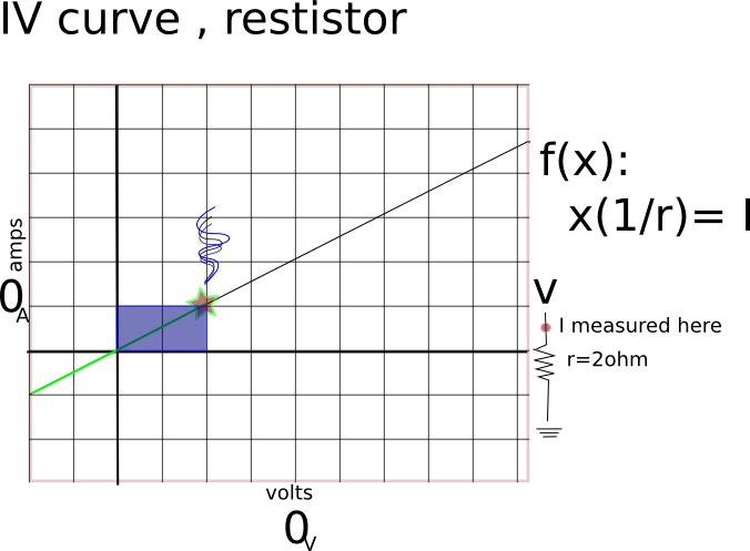
- Ohm's law
- Diagonal IV curve.
- symmetric
ResistorLab
- solder resistors, meter and record;
- compare to ohms law math
Diode
ScaryDataSheetLab
- a favorite led [20]
- LED ( Light emitting diode ) are diodes with a clear case.
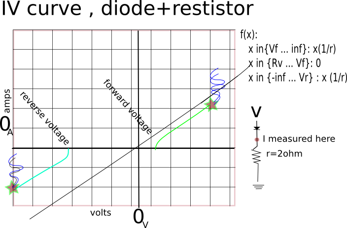
- electrons only permitted to flow in one direction: cathode to anode
- there are exceptions [diode breakdown voltage]
- discontinuous IV curve
- diode logic
- the cathode is marked
- the diode check function of the meter can reveal the correct polarity of a mystery diode with a suspect cathode mark.
Light Emitting Diode
- the short lead is the cathode
- LED's need current limiting (see BlueSmokeLab)
LEDLab
- solder in 1kOhm resistor for the led , although you may use another if you can justify the value
- Solder in the LED, with the short lead towards the ground.
Motor
Printed Circuits
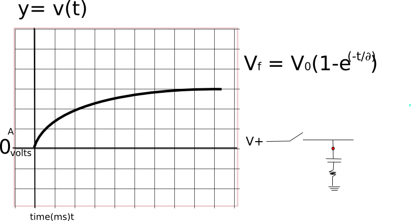
Capacitor
470uf electrolytic cap
Relays/Switches
Codespeak
- SPDT - single pole dual throw
- DPST - dual pole single throw
- 4P10T - ???
- Map this mystery switchLab
Electromechanical relay is a switch that's controlled electrically.
pros
- Easy to design for
- debugging (listen for satisfying click)
- excelent isolation
- high power control/$
cons
- high drive current (mostly)
- noisy (mostly)
- slow
- moving parts (eeew)
a typical relay - map this mystery relay lab
Transistor
PN2222 N channel transistor
little amplifierlab
- class A amp
- DC blocking caps
- bias resistors
- fixed gain
- inverted waveform
Digital Logic
- AND C = A & B
- OR C = A | B
- NOT C = !A
- NOR C = !(A|B)
- NAND C = !(A&B)
- MUX C = select A(n) based on B(n)
IC
LM386 Audio Amplifier [21]


