ElectronicsClass: Difference between revisions
From HacDC Wiki
| Line 104: | Line 104: | ||
==Capacitor== | ==Capacitor== | ||
470uf electrolytic cap | 470uf electrolytic cap | ||
[[Image:capt.png]] | |||
[http://en.wikipedia.org/wiki/Capacitor wikipedia capacitor] | [http://en.wikipedia.org/wiki/Capacitor wikipedia capacitor] | ||
Revision as of 21:19, 18 February 2009
Electronics Class
This class is targeted at the beginner who wants to learn electronics. It would make a fine prerequisite to the Microcontroller Course or the HAMClass
Required Materials
- Soldering Iron (25-30w)
- Solder ( 22ga )
- Bread Board ( or AshClassBoard )
- wire 24ga
- 30ga solid core wire
- Resistors 10kohm
- variable resistor 10kohm linear
- switch [[1]]
- leds (various)
- capacitor 470uf (ish) [[2]]
- pn2222 transistor
- lm386 audio amplifier ic
- 1/8 male phono jack
Read The Fine Data Sheet: They hide secrets in the documentation.
Metering
There are many like it but this one is mine.
- Naming of parts
- metering modes
- restistance - Ohms of resistance
- voltage - Volts
- Current - Amps/Milliamps - check the leads
- diode check - see [Diodes]
- leads - plugged into the right ports?
- metering modes
- Continuity testing
- set the meter to the lowest resistance mode (200ohms or auto resistance)
- reads "off scale" when the leads are unconnected, this is an open circuit
- firmly touch leads together
- reads near 0 if the leads are crossed
- Voltage testing
- set meter to 20Vdc or VautoDC
- touch leads to metered points
- the reading on the meter is the difference in voltages between the leads
Soldering
Hold the cold end.
Soldering ( for our purposes ) is the process of joining electrical contacts with a low melting point metal to make a mechanically and electrically strong connection.
- Restrain long hair/clothing/jewelry.
- Clean both parts of waxes, oils or debris.
- Mechanically fit connections together
- Clean and wet the iron
- Heat both parts until hot
- Apply just enough solder to wet the contact surfaces
- Wait for the connection to shine smoothly
- remove the iron an test the connection
- the meter should find near 0 ohms of resistance between the two parts even when mechanically stressed.
- the meter should read "off scale" to everything that should be isolated
SwitchLab
- use the continuity meter to diagram the electrical layout of the switch.
- solder switch to the board.
- test under power with meter voltage setting
Wire
The basic wire is a pipe through which electrons can flow from the lowest voltage side to the highest (conventional current) up to the physical limits of the wire.
- Current limit via wire gauge [3]
- Voltage limit via insulation.
BlueSmokeLab
Get this out of the way early (and often)
- turn off the switch
- Solder the 30ga wire ends on to the lab 0 area
- stow fingers away from wire
- turn on switch
Resistor
Not like the NYC variety
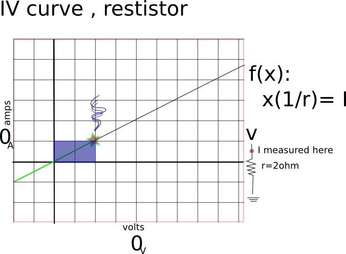
Resistors impede the flow of electrons across them; usually to protect components from excessive current.
- Ohm's law
- Diagonal IV curve.
- symmetric
ResistorLab
- solder resistors, meter and record;
- compare to ohms law math
Diode
ScaryDataSheetLab
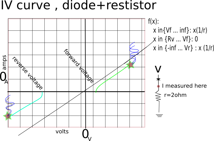
- a favorite led [4]
- LED ( Light emitting diode ) are diodes with a clear case.
- electrons only permitted to flow in one direction: cathode to anode
- there are exceptions [diode breakdown voltage]
- discontinuous IV curve
- diode logic
- the cathode is marked
- the diode check function of the meter can reveal the correct polarity of a mystery diode with a suspect cathode mark.
Light Emitting Diode
- the short lead is the cathode
- LED's need current limiting (see BlueSmokeLab)
LEDLab
- solder in 1kOhm resistor for the led , although you may use another if you can justify the value
- Solder in the LED, with the short lead towards the ground.
Motor
Capacitor
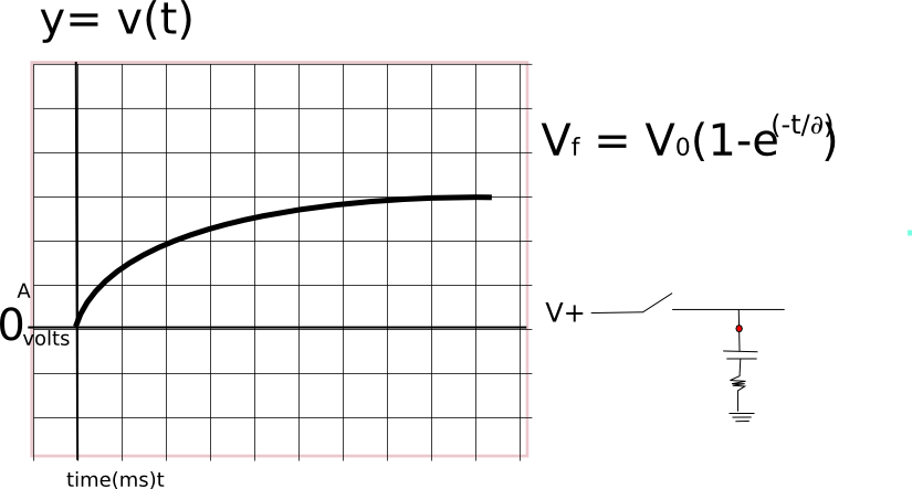
470uf electrolytic cap
Transistor
PN2222 N channel transistor
IC
LM386 Audio Amplifier [5]


