AVR Microcontroller Class 2009: Difference between revisions
From HacDC Wiki
Hexagon5un (talk | contribs) |
Hexagon5un (talk | contribs) |
||
| Line 30: | Line 30: | ||
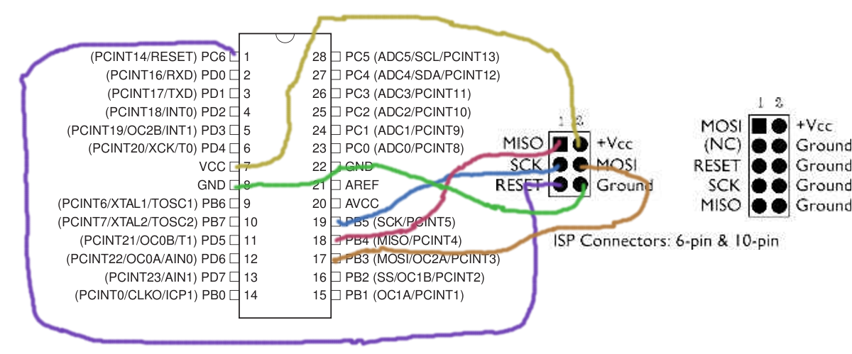
* Wiring Diagram: [[Image:wiring.png|320px]] | * Wiring Diagram: [[Image:wiring.png|320px]] | ||
'''Homeworks''' | |||
* Your kit has 10 resistors and 10 LEDs. If you want, you can solder them together to make [AVR: LED Blinkenlights]. | |||
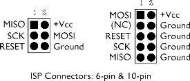
* If you didn't already, make labels for the signal wires. Think of an easy way to remember which go where (into the 6-pin or 10-pin header). And/or make permanent programmer "pigtails" by soldering the signal wires to a 2x3 header in the correct orientation (headers available in the HacDC hackersmart for pennies). | |||
* Play around with the delays in the LED_Demo.c code. Make the blinking faster or slower. Experiment with on time and off time. | |||
== Class 2: Outputs: Bit Math, Cylon Eyes, and PWM Fading == | == Class 2: Outputs: Bit Math, Cylon Eyes, and PWM Fading == | ||
Revision as of 16:17, 17 September 2008
Syllabus, course material, homeworks, photos, etc from an Introduction to Microcontrollers with AVR chips class can be found here.
Also see (and contribute to) Useful AVR Links
Class 0: Introduction and Setup
What the AVRs are, what all the pins do, what they can do for you. Then the toolchain: soldering together the programmer kits, getting the software up and running.
Labs: building the kit and running a test LED flasher. (Almost all lab today, little talk.)
Resources:
- Slides from class: Media:class0.pdf
- ATmega48P Datasheets (get both): ATmega48P Summary Datasheet and The Long ATmega48P Datasheet
- Download the software part of the toolchain: For Mac folks: AVR Mac Pack. For Windows folks: WinAVR. For Ubuntu linux folks: "sudo apt-get install build-essential avr-libc binutils-avr gcc-avr avrdude"
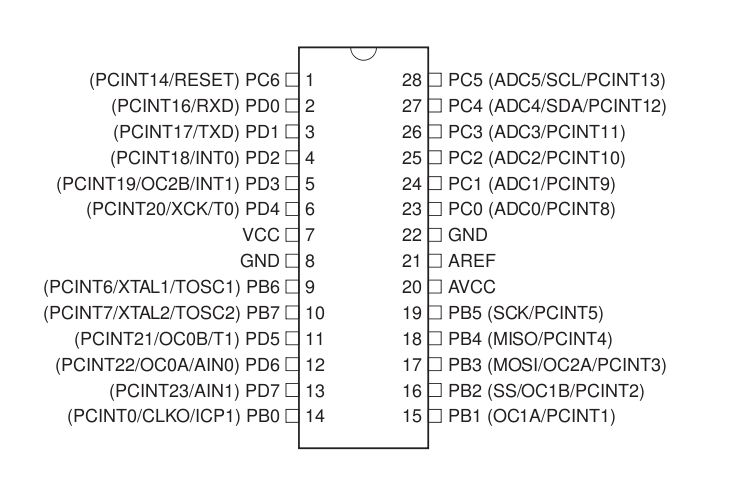
- Programmer and mega48 pinouts:


Class 1: Programmer Hookup and Hello World LED Blinking
Lecture on how the programmer works -- simple serial interface basics. Some basics on avrdude / GCC tools. Hook up the programming interface wire-by-wire to the Mega48 chip and flash it with a simple program. The hook up an LED to the output port and watch it blink!
Resources
- Class notes: Media:class1.pdf
- Wiring Diagram:

Homeworks
- Your kit has 10 resistors and 10 LEDs. If you want, you can solder them together to make [AVR: LED Blinkenlights].
- If you didn't already, make labels for the signal wires. Think of an easy way to remember which go where (into the 6-pin or 10-pin header). And/or make permanent programmer "pigtails" by soldering the signal wires to a 2x3 header in the correct orientation (headers available in the HacDC hackersmart for pennies).
- Play around with the delays in the LED_Demo.c code. Make the blinking faster or slower. Experiment with on time and off time.
Class 2: Outputs: Bit Math, Cylon Eyes, and PWM Fading
How to make chips speak to the outside world, pin-by-pin. Enough C bitwise-math operations to make it work. Pulse-width modulation.
Labs: Visualizing bytes, Cylon eyes, and dimming LED's. Extra credit: cross-fading cylon eyes!
Class 3: Inputs: Buttons and Analog-to-Digital conversion (ADC)
Gather data from the world.
Labs: pushbutton organ, light-dependent theremin. Extra credit: something else!
Class 4: Interrupts and Timers
Interrupts call subroutines when certain conditions are true. Timers let you time stuff. Together, they take a lot of the programming burden off your shoulders, and enable really cool stuff.
Labs: Driving servo motors and/or build a better audio synth, use an LED as a light-source and light-sensor. Extra credit: capacitive touch-switch!
Class 5: Serial I/O
Make the micro speak to your computer (and vice-versa). We can also cover other serial protocols (I2C, SPI).
Labs: Basic serial in/out, data-logging light sensor. Maybe SD/MMC cards? Extra credit: ADC + serial output + Python + laptop = ghetto oscilloscope.