OpticalSubsystems
From HacDC Wiki
(Redirected from OpticalSubsustems)Just as electronic breadboards often rely on integrated circuits (notably OpAmps), external power, and test equipment, optical tables also benefit from more than simple packaged lenses. Here we document the optical tools available at HacDC, many of which are self-made.
Source files are kept at https://github.com/HacDC/HacDCOptics .
Tools
Complex drop-in optical systems, ready to create or analyze complex light fields.
WideBeam
A wide beam of high-intensity collimated light is useful for manually checking the results of complicated optical beampaths. Work in progress for 2" and 8" optical axis modules.
DLPMod
HacDC has access to some DLP projectors, absent working light sources. These can be used as re-configurable image sources and high-speed light gates.
Lasers
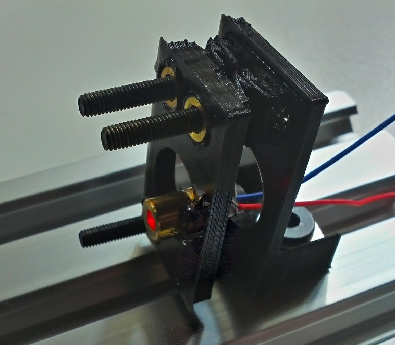
Variety of 2" optical axis laser mounting hardware in progress.
Fixtures
Generic mounting hardware.
Tilt and Roll Platform
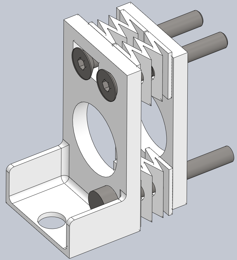
Even if we could afford them, commercial systems are too expensive to permanently dedicate to completed projects (~$500). Instead, we will 3D print or laser-cut a screw-adjusted spring-loaded platform, much the same as the adjustable bed used by many 3D printers.
Elements
Spatial Filter
Work in progress for 2" optical axis modules, with varying diameter pinholes.
Standards
External
Standards set for us by manufacturers.
- Tapped holes, ¼-20" UNC on a 1" (25.4 mm) grid. May be roughly compatible with some M6 on 25mm grid for optical systems with non-critical dimensions.
- Standard optical axis heights include 330mm/13", and possibly 1.15", 1.75", 2", 3.38", 4.5", 6.25", 8" http://www.edmundoptics.co.uk/optomechanics/optical-mounts-plates/lens-mounts/optical-cell-kinematic-mounts/2592.
- Cage square lengths include at least 16mm, 30mm, 60mm.
Internal
Standards we have elected to follow from the above, or have established ourselves, as we build our own tooling.
mirage335
These standards are chosen to permit quick transition between optical table, rail, and cage systems, with only small height-adding brackets.
Stage
Stages directly connecting to extrusions are named "Series20/40/60" depending on the minimum width in millimeters. For instance Series40 mounts require two screws, 20mm apart, and have a maximum width of 40mm, all suitable for mounting on typical 20x40mm extrusions.
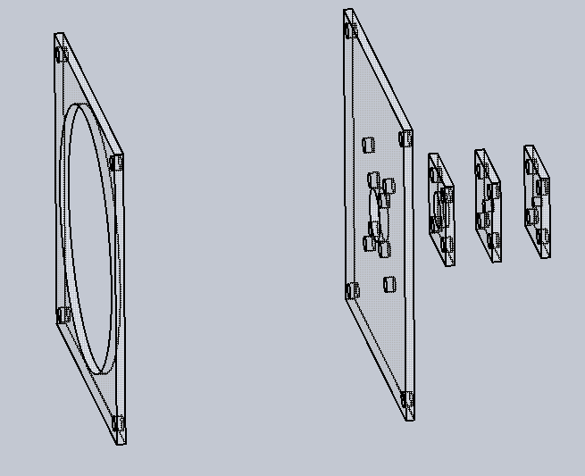
Substages mounted to an earlier kinematic stage or bare baseplate must fit around the rectangular opening for that series.
By default, these standards conform to the "Small" standard under "Optical Table Axis Heights".
| Series | Axis Height | Opening | MaxThickness | Notes |
|---|---|---|---|---|
| TinySeries20 | 15mm | 14x14mm | 6mm | Specialized non-standard axis height. |
| Series20 | 35mm | 14x14mm | 6mm | Specialized non-standard axis height. |
| Series40 | 30.8mm | 18x28mm | 6mm | |
| Series60 | 30.8mm | 28x38mm | 2mm |
Mounting Holes
Tolerances intended for well-calibrated 3D printers.
Table
- Screw diameter - 6mm (M6) to 6.35mm (¼in UNC) .
- Hole spacing - 25mm (metric) to 25.4mm (1in imperial) .
- Hole size - 8mm .
- Hole spacing - 25.2 mm .
Extrusion
- Screw diameter - 5mm (M5) .
- Hole spacing - 20mm .
- Hole size - 5.5mm .
- Hole spacing - 20.25mm .
Optical Table Axis Heights
Standard axis heights are based upon typical hardware for 1" grid optical tables. Mounts for other arrangements, such as a 20series extrusions, should use corespondingly lower heights. Options to mount such hardware to a standard table through intermediate stages, such as 20series extrusions themselves, should be preserved.
Small axis height is typical, and should be assumed unless noted otherwise.
| Element Size | TableHeight | ExtrusionHeight | Comments |
|---|---|---|---|
| Small | 2in/50.8mm | 30.8mm | Intended for lenses up to 1" high, including salvaged projector, disposable camera, and microscope components. |
| Large | 8in/203.2mm | 183.2mm | Accommodates larger lenses, particularly for light gathering and projection systems. |
| ExtraLarge | 13in/330.2mm | 310.2mm | Accommodates modest Fresnel lenses. |
Optical Cage Square Lengths
| Element Size | Height |
|---|---|
| Small | 30mm/1.1811" |
| Medium | 60mm/2.3622" |
| Large | 6.25" |
Reference
- Printed Breadboard - http://www.thingiverse.com/thing:9040
- Aluminum Angle Mounts - http://www.thingiverse.com/thing:38062
- Lens Mount - http://www.thingiverse.com/thing:26752/#files http://www.thingiverse.com/thing:62693/#files
- OpenSource Optics - http://www.appropedia.org/Open_source_optics
- Linear Translator - http://www.thingiverse.com/thing:144838
- Metal Lens Mounts - http://www.edmundoptics.com/optomechanics/optical-mounts-plates/lens-mounts/
- Lasercut Optics Bench - https://hackaday.io/project/10707-lasercut-optics-bench


